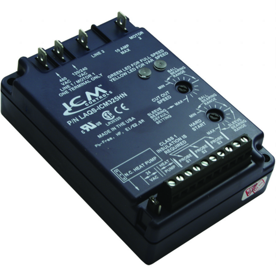
Icm Lr30320 Wiring Diagram
In the next page youll find the ICM connectors pinout with a brief description of each wire. Do not connect the thermostat wires to the control board until System Tests are complete.

Icm203fb Icm Controls Icm203fb Icm203f Delay On Break Timer 6 Wire Leads 03 10 Minute Knob Adjust Delay
Be the first to review ICM220 Cancel reply.
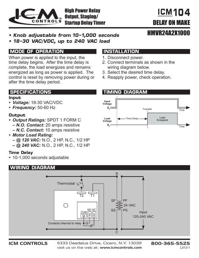
Icm lr30320 wiring diagram. Of our latest products sell sheets and wiring diagrams Cross Reference HVACR CONTROLS REPLACEMENT MODEL ICM PN REPLACEMENT MODEL ICM PN AIR HANDLER CONTROL Vtronics. You might check nordynes web site for a wiring diagram. 16092018 16092018 6 Comments on Icm Lr30320 Wiring Diagram.
Atwood Rv Furnace Wiring Diagram. 401475 ICM340 DELAY ON MAKE TIMERS A-1. Begin component test sequence by ensuring that.
Ignition Control Module ICM Circuit Descriptions. Jeep Wrangler 32rh Neutral Safety Switch Wiring Diagram. 3b7d Icom Microphone Wiring Diagram Wiring Resources.
How to test the ford ignition control module. Hyundai i10 electrical wiring diagram. Power 12 V Circuit.
Time Delay Delay on Make 18 To 240 Voltage 15 Contact Rating Amps Item 4E233. Affix the new wiring diagram label over the existing wiring diagram. The delay on break timer will release the lock and then the delay on make timer will enable the door to open and be held open for a set period of time.
Next Post 17 2014 Ford Truck Trailer Wiring Diagram. Suitable for use with anticipator-type thermostats this ICM time delay relay features a control knob for adjustable time range. System Tests Step 1.
Icm Lr30320 Wiring Diagram. Fuel Pump Wiring Diagram -Single Tank 1996 Ford F150 F250 F350. Each circuit is identified by a letter and this is the same letter that you will find on the ignition modules connector.
2013 Mastercraft Prostar 197 Wtt Engine. 32001 32387 32392 Robertshaw. Delay on break timer wiring diagram download f delay timer wiring diagram.
Make sure to use the correct label for 80 LAPP25 or 90 LAPP26 furnaces. Your email address will not be published. Select desired time delay.
Ellipsoidal Reflector Spotlight Diagram. Previous Post 16 1967 Chevy Truck Steering Column Diagram. Modifying An Icom Hm 152 Microphone For The Flex 3000 Flex 1500.
A wiring diagram is a simplified conventional photographic depiction of an electrical circuit. R200A ICM6500 CONDENSATION CONTROLALARM Water Guard. Delay on break timer wiring diagram 1 icm delay on make timer 1 icm lr30320 1 compressor delay timer 1 delay on make or delay on break 1 delay on break timer definition 1 icm time delay wiring 1 time delay relay 1.
TIMING DIAGRAM ICM2 0C7M89 0 0 0C7M89 Compressor Lockout WIRING DIAGRAM Contactor Compressor Thermostat Switch Input Voltage 7313 William Barry Blvd. Component Self Test 1. Nordyne Control Board Wiring Diagram Icm2805a Furnace Control Module Icm Controls.
AC Air Conditioning Refrigeration and Heat Pump Delay-on-Break Timer - Part ICM203. Ignition system circuit diagram 1998 3 wiring 1995 part gm 8l control module icm test forum buick cadillac 89 park avenue coil to 3800 service tips techniques and standalone harness swap specialties engine problem diagnostics fast start on a turbo 2004 lesabre need diagrams of s fuel injector fiero info boyer key 95 ave series 2 vin c. Fuel Pump Wiring Diagram -Dual Fuel Tanks 1993-1995 Ford F150 F250 F350.
You can find the 1992 1993 ignition system wiring diagram here. Circuit labeled A-Pink Wire. The lockout relay circuit.
Below are the descriptions of what each circuit does. Hyundai I10 Electrical Wiring Diagram and Diagram Also Hyundai Santa Fe Wiring Diagram As Well. 0489661 I Ic 7000 Microphone Wiring Diagram Wiring Resources.
Time Delay on break for compressor. Control wiring and navigation wiring. Model ICM102 UNSPSC 39121515 Catalog Page 3035 3035 Country of Origin USA.
Time delay is factory preset to one specific time 5 seconds for example. Icm Lr30320 Wiring Diagram. The ignition control module ICM has 4 wires coming out of it.
Reapply power check. Boyer Ignition Wiring Diagram Key Diagrams Distributor. Kubota Zd21 Parts Diagram.
2000 Freightliner Fl80 Fuse Box Diagram. Lockout protection relay to help eliminate nuisance lockouts typical of Series 84 and 93 impedance relays. Icom 21 00h Mic Wiring Diagram Wiring Library.
06 Chevy Express 43l Cpu Pinout Wiring Diagram. Totally Free Buick Wiring Diagrams. Dynamic Mic Preamplifier Circuit.
This furnace has 3 heat strips and 3 seqencers i need to have the wiring diagram can you help me. There are no reviews yet. It is intended to provide technicians with the procedures required to maintain and service the unique components of the roush cleantech e 150250350 liquid propane autogas vehicles.
Jensen Vm9510 Wiring Diagram. Country of Origin is subject to change. Delay on break timer wiring diagram.
Fuel Pump Wiring Diagram -Dual Fuel Tanks 1996 Ford F150 F250 F350.
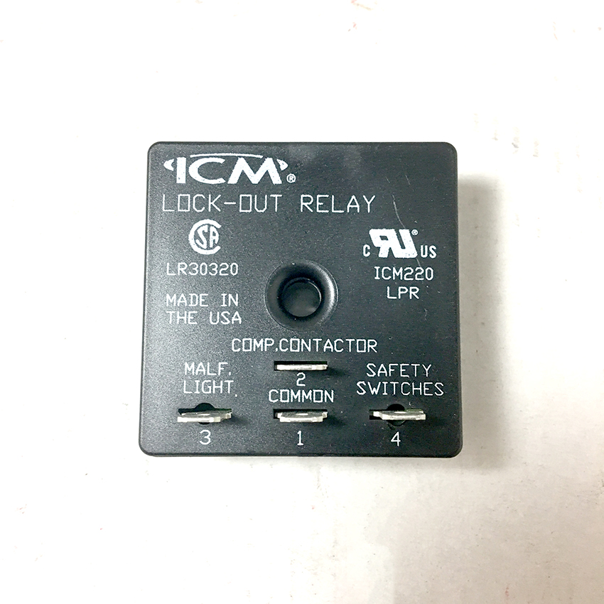
Icm Lockout Relay Icm220b Shortys Hvac Supplies
Delay On Break Timer Wiring Diagram Atkinsjewelry

Icm Controls Icm203fb Delay On Make Timer At Controls Central

Icm203fb Icm Controls Icm203fb Icm203f Delay On Break Timer 6 Wire Leads 03 10 Minute Knob Adjust Delay
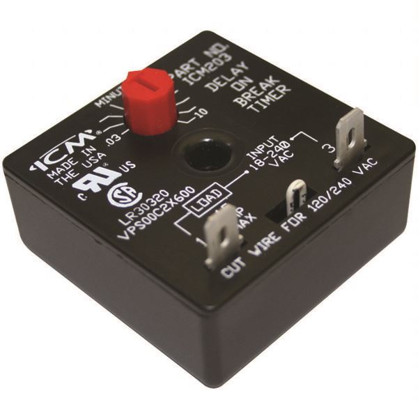
Delay On Break Timer 120v Icm Lr30320 Partsips Appliance Parts And Supplies Partsips

Head Pressure Controller 2 Speed Fan Heating Help The Wall

The Lockout Relay Circuit Youtube

Time Delay Relay Icm203 Delay On Break Timer Made In Usa Product Timer
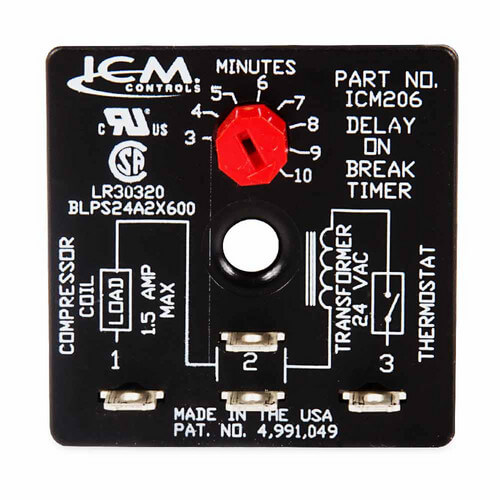
Delay On Break Timer Wiring Diagram Atkinsjewelry
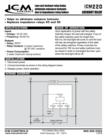
220 Icm Lockout Relay Manualzz

Furnace Control Boards Jackson Systems
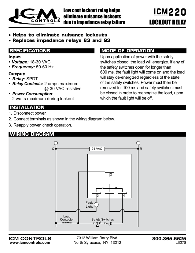
220 Icm Lockout Relay Manualzz

104 Icm Delay On Make Hmvr24a2x1000 Manualzz

Hvac Relay Training Bypass Timer Youtube

Hvac Delay On Make Timer How It Works How To Wire Compressor Staging Startup Delay Timer Youtube
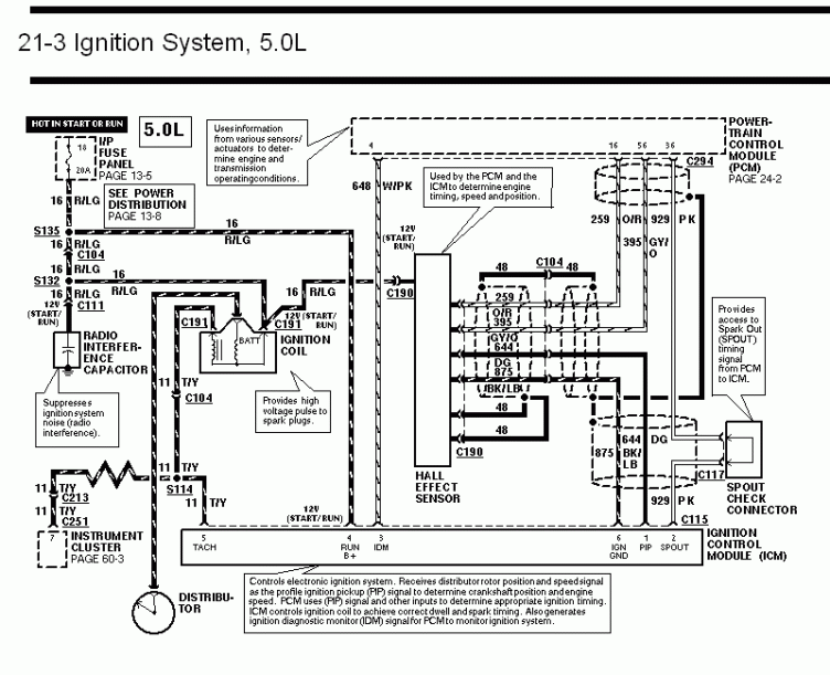
Diagram Ford Icm Wiring Diagram Full Version Hd Quality Wiring Diagram Snadiagram Segretariatosocialelatina It

